Sunday, December 31, 2006

So long 2006, see you on the road in '07


(photos: collection of Everett Barnes)

Wednesday, December 27, 2006

More than you ever really wanted to know about sidedraft elbow clamps

I never knew there was more than one version of the clamp that holds the rubber air intake elbow to the 32-PHN air cleaner, but while putting things back together I realized I had two very different clamps to choose from:


I don't know if one is a later design development or if they were just from different suppliers. I have an owner's manual dated 11/61 that shows the one on the left, but I'll probably end up using the one on the right. It works better and it's a more elegant design solution overall.

A very different clamp was shown in early press photos and the 1961 edition of the VW 1500 Workshop Manual:


It seems to be a rubber strap. This design must have been superseded just before production began. It does explain that odd indentation found on the top of most sidedraft air cleaners though.

Air cleaner restoration

Knecht air cleaner, before and after:


It was pretty rough to begin with. I did some very careful straightening of the dents I could reach, then smoothed out the remaining problem areas with lots of sanding, painting, more sanding, and more painting. With the reproduction decal applied it's done.

Sunday, December 24, 2006

Brussels, 1969


If you look closely (click to enlarge) you'll find a Type 34 Ghia and a Variant, as well as a new 411, several Beetles, and a Type 1 Ghia. Merry Christmas!

Friday, December 22, 2006

Why a VW 1500 Karmann-Ghia?

Q: Why was I drawn to a somewhat sporty 2-door rear-engined car from the early '60s with a pronounced beltline?


A: Behavioral conditioning. Here's my family having a picnic at a park in Santa Barbara, California in April 1963. That's a 9-month-old me in the playpen trying to get a better look at my dad's '62 Corvair convertible.

Sunday, December 17, 2006

More progress

I had to sideline the Ghia project for a while for some much needed roof repair and general waterproofing on the house (it doesn't rain very often in Southern California, but when it does...), but this weekend I was finally able to spend some time with the engine. A few weeks ago I was stopped cold by stripped threads in the case. I was trying to install the front half of the fan housing and the case threads for the left side mounting bolt decided to let go. I tried drilling and tapping the threads a little deeper and using a longer bolt but the few threads that were left wouldn't hold. I needed to find the strongest, most permanent solution since these bolts are notorious for coming loose over time anyway. Jim Adney on the vwtype3.org list suggested using thread-locking helicoils. I wasn't familiar with the thread-locking version, but a quick Google search led me to them.


Locking helicoils aren't the easiest thing to find but they're a great thing to know about. They have an eccentric coil that holds the threads in tension, keeping the bolt from loosening. I was able to find 15mm M6 inserts, which are another half as long as the ones that are normally available.


Here's the right side one installed. I decided to do both for peace of mind, since the magnesium alloy case material is relatively soft. I was worried about drilling too deep on the right side -- the left side isn't a problem because if you drill too far it will break through to an area outside the case, but on the right side it will break through inside. Jim was kind enough to measure the case thickness on an old case in his shop, and on the right side it's only 20mm thick. A slight miscalculation would mean splitting the case to clean the shavings out, so I decided to drill only as far as absolutely necessary for the helicoil tap (17mm), and while it was a little nerve-wracking it all went according to plan. Now I can use 20mm bolts instead of the original 15mm, and since the helicoil threads are stainless steel the fan housing mounting will be stronger than what came from the factory.


I used the factory tool VW 177 to center the front half of the fan housing. The procedure is to position the centering tool, then rotate the fan housing counterclockwise until it stops at the split in the case, then tighten the two main bolts. This should be done with the crankcase breather stand and cooling tin screws loosened.


VW originally used shake-proof star washers with the fan housing bolts to keep them from loosening. They're a little funky but I figure VW knew what they were doing.


Here are the fan housing, fan, and pulley installed.


I used the factory 6V flywheel lock VW 215b while torquing the fan pulley bolt. I tightened the bolt to 36 ft. lbs. as recommended by Henry Elfrink's Volkswagen Type 3 Technical Manual, but Russ Wolfe pointed out to me that it should actually be 90 or 100 ft. lbs. according to factory specs. John Muir's How to Keep Your Volkswagen Alive also contains this error, so Type 3 engine builders beware. The Muir book is widely known to have errors, especially in the information about Type 3s, but it's a surprise to me that Elfrink got it wrong. He's usually pretty reliable. Thanks for the heads up, Russ!


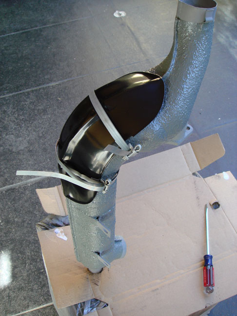
The air intake housing is in place.


The generator and coil too. The intake manifold is placed loosely in position for the time being -- the manifold and carburetor are next on the agenda. It's starting to look like a Type 3 engine again.

Tuesday, December 12, 2006

Phantom views

VW often provided nice phantom views of its cars in brochures to help explain their features and to illustrate efficient use of space. These are from brochures printed in 1961.


This one makes good use of ink overprinting to make its point.


A comparison of the sedan and Karmann-Ghia. Passenger space, luggage space, and weight distribution are color coded for easy visualization.

Monday, December 11, 2006

VW 1500 on holiday, 1960s

Caravaning in a 1962 VW 1500 sunroof and Eriba Faun trailer sometime in the 1960s. That's a pretty big trailer for 54 horses.


Saturday, December 9, 2006

Automotive News announces "big" VW, March 1961

The bi-weekly auto industry trade journal Automotive News broke the VW 1500 story in the US in March 1961.


Unlike The Autocar they got their facts about the 1500 straight. The article notes that its public debut would be at the Frankfurt show in September, and that VW had no plans to market the 1500 in the US.

Thursday, December 7, 2006

More early engine reference

Many thanks to Andy Holmes for sending these early 1500 engine images. Andy is the owner of an immaculate 1965 1500S Karmann-Ghia and is currently restoring an early '62 1500 Ghia. He's well on his way to having the bodywork completed -- check out Andy's restoration blog to see how things are coming along.


The first is factory press photo with another cutaway view of an early engine. It's interesting for its detail but also for the features it includes that didn't make it into production, such as the crankcase breather arrangement described here, the rubber strap that holds the top of the air cleaner in place (a metal clamp on production cars), a different tailpipe mounting arrangement, and the unusual plug wire separators that were used on VW's 36-horse engines circa 1960 (one visible just below the air cleaner). Andy's favorite feature: the artist's dramatic addition of a spark igniting the fuel mixture in cylinder #3 (upper left).


This is the engine bay of one of the 1500s on display at the Frankfurt Auto Show, the 1500's official public debut in September 1961. This photo provides answers to some questions I've had about when certain features were introduced. For one thing, it proves that the unusual features seen in the press photo above were all dropped sometime before full production began. It also confirms that the Knecht air cleaner should have a small washer under the wingnut. Air cleaners produced by Mann for the 1500 had a large, specially shaped washer that would have been hard to lose, but I've never seen a Knecht filter with a washer. Must've all gotten lost during service. The air cleaner doesn't have a connection port for a crankcase breather hose, so that supports the idea that the port was introduced around the beginning of 1962. Both of these images also show a full-sized Bosch coil. There's been some debate about whether the early engines came with a long or short coil, but these images seem to settle it. Interesting that there's no insulation under the engine trapdoor -- I wonder when that was added?

Thanks again, Andy. The obsessive engine detailers among us are much obliged.

Sunday, December 3, 2006

Progress

Things are starting to come together. The oil cooler, distributor, fuel pump, and crankcase breather stand are in place. I used Gasgacinch on the paper gaskets to minimize leaks.


I found an NOS '62 oil cooler at Bill and Steve's in Downey, California. They used to have a box full of them, but I think I got their last one. Bill and Steve's was the center of the Type 3 universe in the late 1980s and early 1990s. Now it's just a good neighborhood auto parts store that specializes in aircooled VWs, which is becoming a rare thing these days. They still have a small display case of hard-to-find Type 3 parts. Yes, I forgot the carb return spring bracket. I realized it as I was taking the photos.


I cleaned up the F&S clutch disk and pressure plate and reinstalled them. They are date stamped 1989 and the previous owner had them installed in 1992 according to her records. The car has only traveled about 5000 miles in the last 14 years, so they're almost new.


The heat exchangers are installed and the newly powder coated tin is in place. The next step will be to install the fan housing so I thought I'd get a shot of the early case's part number while I had the chance. Won't be seeing it again for long while.


Or so I thought. While I was installing the rear half of the fan housing the threads in the case stripped when I tightened the left mounting bolt. Tapping the hole deeper and using a longer bolt failed too. It's helicoil time.

VW workshop tools

I've started collecting VW factory workshop tools. I've been looking for Type 3-specific tools in particular, but also general VW tools that have an application on the VW 1500. Here are some of the tools I've found that have been put to use in my engine overhaul project:


Clockwise from the left: VW 176, Type 3 fan puller; VW 215b, 6-volt flywheel lock; VW 113, thin 27mm wrench that the VW Workshop Manual recommends for the generator pulley nut; VW 177, Type 3 fan housing centering tool; VW 178, special 13mm wrench for the lower sidedraft carburetor mounting nut; and VW 170, crankcase breather socket. VW factory tools were made by several different manufacturers. Most of the tools pictured here were made by Matra, but the carb wrench was made by Lucas. There may be other tools that will do the jobs that these will, but these do the job better.

The tool I'd really like to have is VW 660, the Type 3 timing gauge. Due to the design of the Type 3 fan and pulley housings timing the engine can be a little tricky. Timing by eye is possible but it involves getting the work light positioned just right, standing directly over the timing hole, closing one eye, and lots of luck. VW realized early on that a gauge would be a big help. There are several different versions of the gauge. VW intended them all to be made locally, but I think some may have been manufactured too.


The simplest one is just cut out of flat metal stock. Henry Elfrink's Volkswagen Type 3 Technical Manual shows a photo of the gauge in use and provides a plan drawing so you can make your own.


A more elaborate version of VW 660 is shown here (photo courtesy of The Samba's image gallery -- I think this one might belong to Mr. Everett Barnes himself). It features a spring clip that holds the gauge in place, leaving your hands free to actually do the work. Plans for an even more elaborate version of VW 660 with a built-in timing light can be found in VW's Workshop Equipment for Local Manufacture manual, which someone has helpfully posted online. The site is a great resource. Eventually I'll make my own VW 660 gauge, but for now I'm still eyeballing it.

Saturday, December 2, 2006

VW 1500 engine cutaways

Here are some nice cutaway drawings of early 1500 engines.


This one is from the 1961 edition of the VW 1500 Workshop Manual.


I'm not sure of the source for this one, but I think it's pre-production since it has features that were never combined on any production engines, at least as far as I know. It shows a crankcase breather tube, which in some pre-production photos is shown connecting to the air intake instead of the air cleaner. I don't know if this arrangement ever made it into production -- if it did it would have been on only the earliest cars produced in late 1961. The heat riser valve is also pictured, but that wasn't actually introduced on production cars until late 1962.

Friday, December 1, 2006

International Auto Parade, 1962

I'm a sucker for those old auto catalogs from the '50s and '60s that show every car available in the world in any given year, including Automobile Year, Automobile Revue, World Cars, and International Auto Parade (a.k.a. Auto-Universum). They tend to follow a standard format that consists of a general overview of the automotive year with articles about new trends, detailed reviews of particularly notable models, and postcard images of the cars of the world accompanied by technical specs, interspersed with lots of full color ads. I try to pick these up whenever they're cheap.


The dust jacket of the 1962 issue of Auto Parade featured the new VW 1500.


Here are the new 1500s along with a Type 1 Ghia in the same issue. Ruby Red seems to have been the color of the year. For some reason the 1500 Ghia didn't appear until the next issue in 1963.

Thursday, November 30, 2006

The longblock returns

I picked up the rebuilt longblock from Mauricio Velasquez, who sourced the machine work and did the final assembly. Mauricio runs Jomag, an aircooled VW shop in the Silver Lake district of Los Angeles. Back in the day he had a nice moss green Cal-Look Notchback that got covered in the VW press and placed in the local shows, so he's fluent in Type 3. If you live on the eastside of L.A. and need a fair and honest mechanic for your aircooled or watercooled VW, give Mauricio a call.


In the end it turned out there was no obvious cause for the sudden compression loss, just wear and tear and probably a case stud or two that let go just enough to cause trouble. Just about everything was salvageable. The case was align-bored and case savers were installed. It turned out to be a routine overhaul.


The original '62 311101301A cylinders were put back into service. My original plan had been to move up to 85.5mm pistons and cylinders because I assumed the old ones would be too far gone, but it turned out that they were within the wear limits, so I decided to reuse them since they've always been with the car. There must be only a handful of cars out there that are still running on these early cylinders. One piston ended up having a hairline crack and had to be replaced, but luckily I was able to find an NOS 83mm 1500 Kolbenschmidt piston in the Samba classifieds from seller Bob Sepulveda.


I was worried that the heads might be cracked, but they came back from the machine shop with a clean bill of health and looking new. What a relief. We were even able to keep the long rocker studs. You really know you've got a 1500 when you set the valves at .008".

Now the final reassembly can begin.

Bosch ZV/PAU 4 R 6

If you have an old Bosch cast iron distributor and it needs a rebuild you call Glenn Ring. That's all you need to know.


Wednesday, November 29, 2006

Heat exchanger restoration

The Ghia's heat exchangers were in surprisingly good condition after 44 years of use. All the grease and grime that had been allowed to build up on them over the years protected them very well from rust. Here they are just after being removed from the engine, with the lower cooling tin still attached:


The small pieces of tin at the right and left were only used through the 1963 model year. They had been installed on the wrong sides as shown here. A broken mounting tab on the right heat exchanger had to be rebrazed before ceramic coating.


The heat exchangers had collected a lot of debris blown in from the fan housing over time. I pulled out a lot of junk including cardboard, feathers, insulation from the engine trapdoor, and even a metal intake manifold gasket. Next I had to strip the exchangers down and degrease them.


I made note of the way the stone shields were attached before taking them off.


I knew early heat exchangers had sprayed-on insulation (the more familiar asbestos wrap was introduced in April 1963), but as the grease came off I was surprised to see that what was left of it was a metallic gold color.


Here's a sample of the sprayed coating that I saved. It's about 1mm thick and flexible. I'm sure it's mostly asbestos. The dust from this stuff is not something you'd want to be breathing in. I did some research on substitutes for the coating and settled on Lizard Skin ceramic insulation. It's not cheap but it has properties that make it a good choice for the job: good heat and sound insulation, withstands temperatures to 500°F, water based and non-toxic. I applied it with a brush over ISP West's ceramic coating, recreating the original texture, and then gave it several coats of engine enamel. I considered painting the insulation gold like the original, but the only hi-temp gold paint I could find had a little too much 24-carat bling for me, so I settled for gray:


The next job was to reinstall the freshly powder-coated stone shields. NOS straps were sourced from BerT3 in Belgium. I considered buying bulk strapping from a source like McMaster-Carr (a highly recommended source for industrial supplies), but when I added it all up Bert's NOS straps cost only a little more. Always use NOS parts when practical! Here's the installation procedure:


Position the shield and straps loosely. VW put the clamps inboard.


This detail shows the way the straps should be threaded. The strap wraps around the heat exchanger once, threads through the rectangular hole on the clamp, then wraps around a second time and threads through the cotter key. Pull in the slack and then trim off some of the excess strapping. Then tighten the key with a screwdriver a half turn at a time, stopping to adjust the strap and reposition as necessary as you go.


Here's a shield clamped in place.


And both finished heat exchangers ready to install.